The objective for this project was to build a simple two band qrp radio, starting with some simple math:
   LO      2*LO   IF           FREQ OPERATION
   -----------------------------------------------
   3.040          4    -->   3.040 + 4 =  7.040 mhz
  (3.053) 6.106   4    -->   6.106 + 4 = 10.106 mhz
With a local oscillator in the 3 mhz range and an optional frequency doubler, and an IF of 4 mhz, one can provide coverage of both 40 and 30 meters.
Those hams on QRP-L mail list are pretty infectious with their enthusiasm, and so an idea was born for a manhatten style 2 band radio.
But then I found the Elmer 101 series about the SW40 rig on the Web. The schematic was also found on the Web. It uses a 3 mhz LO and 4 mhz IF. Here was all the hard part of the design already done for me. And the value of the kit of parts with a printed circuit board - who could pass on that. It was decided to get a SW40 and modify it as needed. Orignal idea was to use a MC1496 for a doubler - no tuned circuit parts needed.
The wait for the SW40 was quite long.....
Those guys on QRP-L are infectious; I learned that Analog Devices would give hams free samples. So I asked for and received a couple of AD9833 parts. I picked the AD9833 for two reasons, low power and only 10 pins to solder.
While waiting for the SW40, I played with the AD9833. It's small. The first dead bug attempt at wiring was a failure. So I mounted the 2nd device to some old etch, 5 pins to a surface mount area with the correct pitch, and the 2nd set of 5 pins were wired with #30 wire wrap wire. I then checked and fixed any shorts and covered the whole mess with epoxy. First experiment showed the device was operational.
The Elmer 101 makes use of pspice, so I downloaded that and spent quite some time modeling changes to the SW40. Changes needed were:
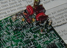
The output filters were tried first. The eliptic filters that worked so nice in pspice, were not so good. I suspect the inductors were not accurate enough. I tried the tapped filters and finally settled on a combination filter with L3 at 1 uh, L4 at .7 uh with a 100pf in parallel, and 220pf 470pf 220pf for C37 C38 and C39. Compared to the SW40 output filter, my filter lacks good rejection at 14mhz. I intend to follow the output with my BLT tuner which seems fairly high Q and should help with the 2nd harmonic when operating on 40 meters.
It was decided to stuff the board with all the parts that didn't need experimental changing. Also the dds was nibbled from the scrap etch and mounted to a board with a PIC for a controller.

Then I experimented with just changing C4 C5 and C6 in the vfo and wondering if it could be made to work on 3 mhz and 6 mhz. It did work but was very unstable at 6 mhz. Just breathing would send the frequency up and down about 500 hz.
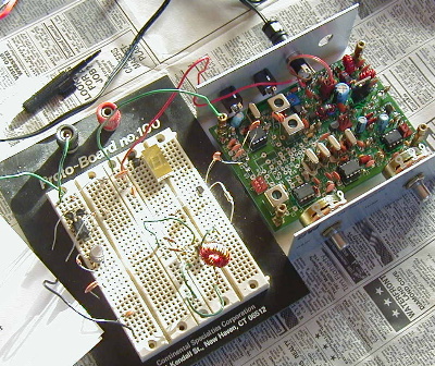
The dds was tried as a LO.
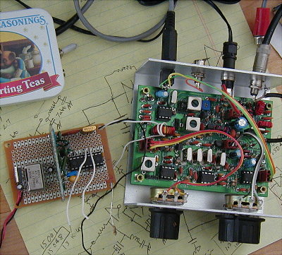
That seemed promising, but I was regretting buying the enclosure kit as things would be tight if the dds was used. I separated the dds from the controller I had made and epoxied it the main board with a ribbon cable over to the controller. Instead of a dds lowpass filter, I tapped the output of the dds down at 10 turns on a 30 turn inductor looking for a 200 ohm to 2k ohm impedence match. This inductor is tuned with some switchable caps to both 3mhz and 6mhz.
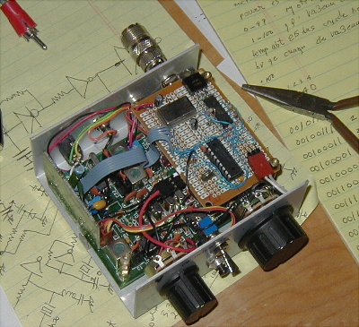
The output of the tuning POT was fed to a quad comparitor to give up/down signals to the controller. There are two tuning rates depending upon how far one turns the POT from center. RIT and frequency announce functions were added with a couple of switches on the front panel. The final transistor was changed to a TO39 package device as it required less drive. (a spare final from the argonaut). The bandpass capacitors were mounted on pin headers removed from computer scrap boards. Changing bands is probably a little less convenient than a Sierra rig. One needs to open the case and remove or place 6 jumpers.
To do someday - the 25.175 TTL oscillator I used from an old vga video board draws a fair amount of current. I need a low power oscillator and then the 7805 regulator can be replaced with a low power version.